Sherwood Ranger - Fuselage - 7
*This web site is NOT owned or managed by G-TLAC. G-TLAC is not responsible for the content unless explicitly stated. See Disclaimer.
9/9/12 - rudder pedals
1/3 hr - sliced the 3" x .125" square tube into rudder pedal sized pieces. Had the chop saw out for another household task, and the table saw would make a good table for part of that task... so used the chop saw to cut off a length of the square tube. Used the table saw to rip that down to two 1" deep U-channels. Then used the chop saw again to cut each length of U channel in half. Just like that, 4 rudder pedal blanks. Now there's going to be a bunch of lightening holes added, but that was MUCH quicker than the same job on the bandsaw.
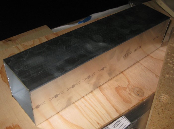
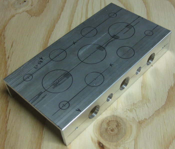
Square tube stock.
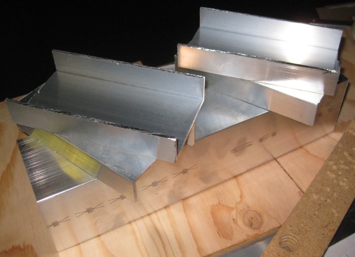
Cut down to rudder pedal blanks.
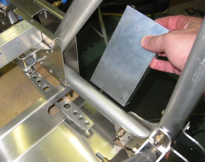
Approximate location of pilot's rudder pedal.
9/10/12 - rudder pedals
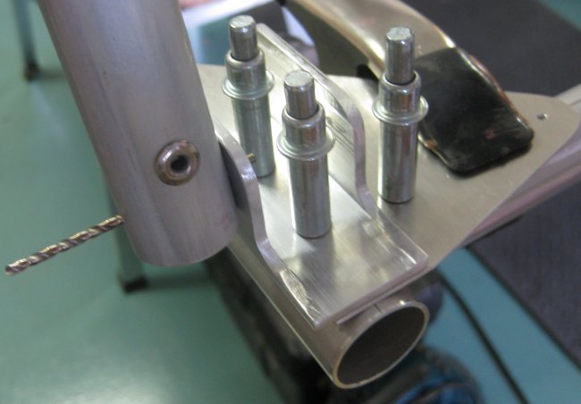
3/4 hr - marked one pedal for attachment and lightening hole locations and started drilling. This may be spending too much time on something I am not sure will even work, though I am curious how much weight comes out of a pedal blank with the holes.
9/11/12 - rudder pedals
3/4 hr - drilled the first pedal and while waiting for it to cool between holes, marked the hole locations on a second pedal. Rounded off the corners, deburred, and sanded and scotchbrited the edges. After all that (21 lightening holes), exactly 1.00 oz comes out of the part. Over 4 pedals, that's 1/4 pound, so I guess I'll keep drilling.
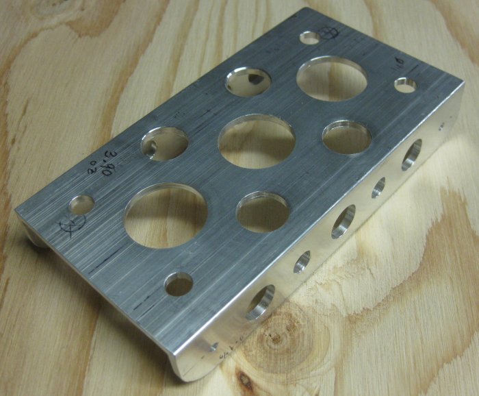
First pedal drilled. All those holes? 1.00 ounce.
9/12/12 - rudder pedals
1/2 hr - more marking and drilling.
Second pedal partially drilled. Learned from the first one to do the sides first. Doing the face first, the pedal flexes some when drilling the sides.
9/13/12 - rudder pedals
1/2 hr - more marking and drilling.
9/14/12 - rudder pedals, etc.
1/2 hr - more marking and drilling, and laid out some doublers for the cutouts in the pilot foot rests.
9/15/12 - forward section
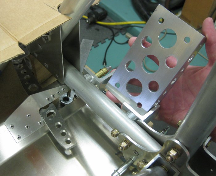
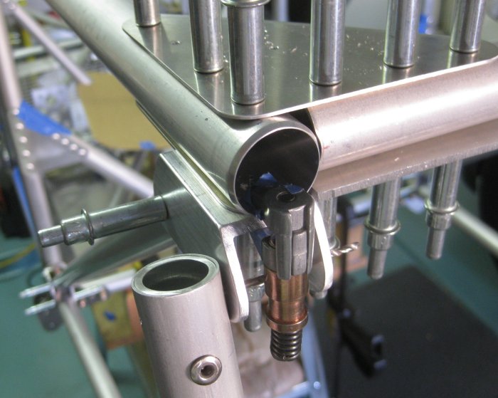
1 1/4 hr - finished drilling on the lower end of the replacement FT20. The holes for FT20 in the outboard gusset plate were clearly in a different position than the original - not sure what is causing that, but there may be something in the geometry of all this that doesn't work out exactly, and this is the point where it comes out. Anyway, got the 1/4 inch bolt through. Then continued work on the upper firewall cross beam. The engine mount bolt on the right side fit well with the insert in the upper longeron tube (a slotted insert that prevents the engine mount bolt from rotating). On the left side, either the slot in the insert was offset (not likely) or the bolt hole through the cross beam was offset slightly. Either way, the bolt head would not nest into the slot in the insert. So I pulled the insert out and filed on the side of the slot that needed clearancing. Several iterations of this and I got the engine mount bolt with a nice fit in the insert. Didn't see a reason now not to tap the cross beam into place and put the bolts through for the final time. (Probably will see a reason later to take this all apart...) The bolts actually went through this effectively solid stack pretty easily. Not drop in, but no major bashing either. Solid stack: Firewall U-channel, U-channel insert, gusset plate, upper longeron tube, tube insert, firewall bolt anti-rotation insert (halfway there), tube insert, upper longeron tube, gusset plate, U-channel insert, U-channel, and on the bottom side, another U-channel bracket for a diagonal tube. That stack is a solid 1 5/8" thick. Clecoed the upper forward fuselage bay diagonals into place (FT27).
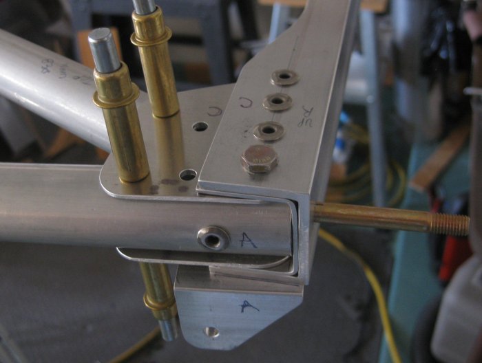
Bolt through all that stuff, right side. Will need to pull the u-bracket back off the bottom to install rivets in the bottom of the gusset plate. Bolt with nothing on it sticking out to the right is for the engine mount.
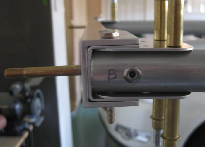
Bolt through all that stuff, left side. So you can see 6 layers of flat material - 3 above and 3 below the tube, but the tube itself is double-walled with an insert, and there's a 3/4 inch diameter insert inside of that to keep the engine mount bolt from rotating, and there's a .125 thick u-channel bracket that goes on the bottom (not installed). That is a solid 1.625 high stack of metal - no air.
3/4 hr - lay out the gussets for the pilot foot rests. Cut them out of .125. Drill 1/2 dia. hole for corner radius, trim perimeter of part to hole. More drilling on the rudder pedals.
9/17/12 - pilot foot rests
1/3 hr - filed / sanded the edges of the gusset parts, pilot drilled the holes.
9/18/12 - thought experiment
On one side, having a little bit of time to work on it most days has the big disadvantage of not really getting into something and cranking out a lot of work at once. But the other side of that is there is a lot of time for your mind to get ready for the next little work period. So today, I remembered that the plans show a washer under the head of the engine mount bolts - the ones that are now anchored by the through-all-that-stuff bolts. Not that I couldn't take them out, but it would be a pain to get all that stuff lined up again, just to add some washers. How to check? Measure the bolt length. Using a caliper? No, how about just using the other engine mount cross beam with the bolts (with washers) already in it. Just hold up the other cross beam and see if either bolts are longer, or if they are the same. So got home and did that. Whew. The bolts now captured are the same length as the loose ones in the other cross beam. And double assurance, those I found on the table already in the beam with washers in place, so I likely did that to the beam that is locked in position as well. And, triple assurance, I can convince myself that I can actually see the washer on the right-side bolt by looking through the small gap between the end of the upper longeron tube and the engine mount cross beam.
1/2 hr - did a little more drilling on rudder pedals. Got tired of that, so drilled the foot rest gusset plate to the right side foot rest. Left side will need a little clearance to the fuselage frame tube. Riveted the small gusset plates at the bottom end of the FT20's. For the one on the left side that was reworked, the bolt still doesn't go through the outboard plate perfectly perpendicular, so I will make up an angled washer from some of the wedge stock left over from the lower u-bracket attachment locations.
9/19/12 - rudder pedals
1/3 hr - drilled the gusset plate to the left foot rest. Drilled some more on the rudder pedals. Looked at the forward fuselage assembly for a minute to try to determine what could be riveted next, if anything. Looks like further progress hinges on getting the upper members of the center box drilled to final size. That way, the FT20's can be permanently attached? (Not if I use the factory fiberglass fuselage top.)
9/23/12 - ordered parts
After a day of not feeling so good, then 2 days of a home improvement project, at least I got some parts ordered. These will allow further progress on the rudder pedal installations, as well as a few things that will come into it farther out. I figured out that Spruce has parts called saddles that fit right into some locations that the plans show. Though there are quite a few other parts that would appear to need a ball-end mill to make that are not the simple saddle shape that Spruce sell.
9/25/12 - pilot foot rests
1/3 hr - up-drilled, deburred, cleaned, and riveted the gusset plates to the pilot's foot rests. Still a little leery of just riveting these on - want to fit the landing gear upper v-brace to see if the foot rests will clear that because it would be more difficult to add clearance to the foot rests with them riveted on to the structure.
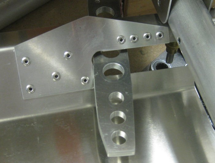
Right side gusset riveted on. Increases cross section where it turns the corner. Also acts as a stop for the brake pedal.
Left side gusset riveted on.
9/26/12 - pilot foot rests / rudder pedals
1/2 hr - got the order from Spruce. The Aluminum saddles are just the thing for the rudder pedal mounts. Cut one down to clear the central frame gusset plate. Checked an oilite bushing in one of the 5/16 lightening holes - looks like the bushing OD expands a little near the flange, so by tapping it into the hole, it will stick to the rudder pedal and rotate around the bolt, just like I wanted. So I drilled 2 mounting holes in the most finished pedal to 5/16 and set the bushings in the holes, seating them down with a few light taps of the rubber hammer. Put a bolt in and it clears without sticking. So this should work ok. Remembered that the "V" for the landing gear suspension also must clear the pilot foot rest plates, so I dug out those parts to see if any more clearancing would be needed. Rather do that now then when the foot rests are riveted to the structure. Sure enough, the "V" will require more clearance on the pilot foot rests. So I'll do that, then I think these foot rests can be riveted on.
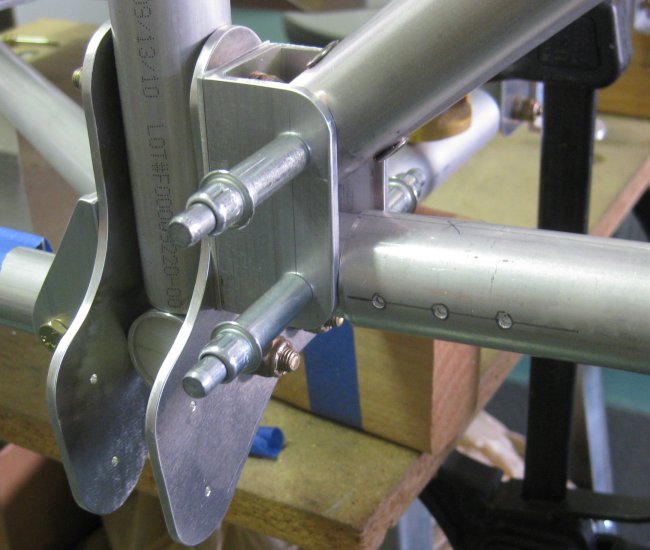
9/27/12 - rudder pedal bracket
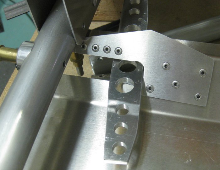
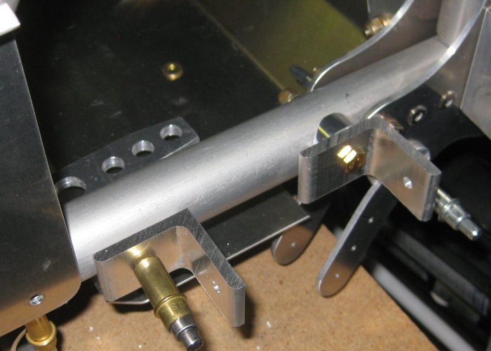
1/2 hr - did some calculation to determine the location of the rudder pedal bracket mounting hole on the bracket. 0.608" from the outside of the L to the center of the hole puts the bracket right against the flat of the 1/4" bolt through the forward frame gusset plate. This bolt has a washer under the head, so a small relief was filed into the bracket. This positions the rudder pedal outboard of the bracket mounting holes, which is essentially what the welded tubular rudder pedal also does. Cut two 1" wide brackets from the 1.5 x 1.5 x .188 angle stock. Will locate the hole in the other bracket later.
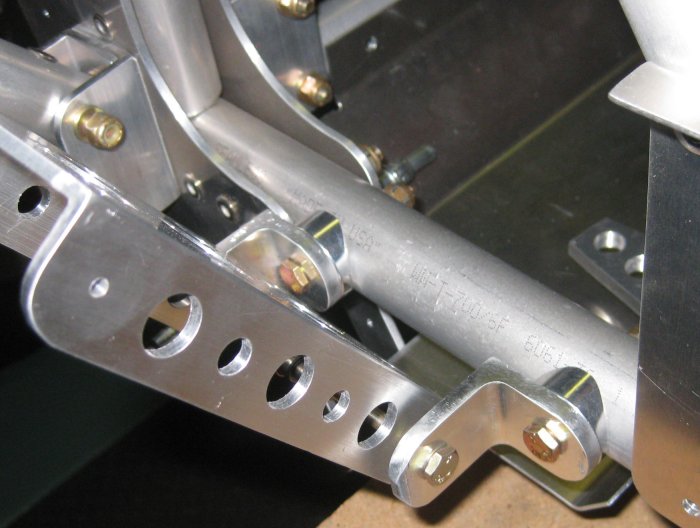
Saddle spacers clecoed to the fuselage frame tube. On the left, the outboard rudder pedal bracket.
Forward looking aft. The small brackets hanging down from the left in this view are for the landing gear V brace. The two different angles of the brackets - near bracket is approximately the angle needed. The far bracket - is limited by contact with the pilot's foot rest.
Looking at the rudder pedal bracket from a little more outboard, I positioned the bracket attach hole so the bracket would be up against the 1/4" bolt for the fuselage gusset plate. This does 2 things - puts the bracket as far outboard as it can go (putting the pedal as far outboard as it can go), and it might keep the bracket from rotating on its attach bolt.
9/28/12 - rudder pedal bracket
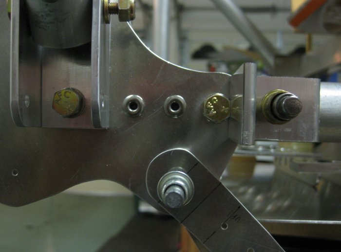
1/4 hr - measured and drilled the mounting hole for the inboard bracket. Checked the fit. It was intended for a single AN960L (1/2 thickness) washer to be needed as a spacer on each side of the pedal, but it looks like it may have turned out slightly wider than that. In any case, both brackets with the pedal attach leg to the outboard side does a good job of centering the pedal on the foot rest panel. I'm not sure I like that the pedal is so far forward of the brake, but this positioning is essentially the same as what the plans show for the welded tubular pedal, so it probably works better than it looks at this point.
Rudder pedal brackets temporarily in place and pedal in position.
9/29/12 - pilot foot rests, rudder pedal brackets, seat rails
3/4 hr - cut blanks for the LH pilot rudder pedal brackets. One of the 4 saddles for this location was the wrong size from Spruce. Called them, they will send out another. Trimmed the pilot foot rests an additional 5/8" on each to clear the landing gear suspension V brackets. Looks like a reasonable amount of clearance now, and this portion of the foot rest is under the cross tube, so neither the brake pedal nor any foot will get into that area anyway. Came up with a concept for a bracket for securing the front seat back to the seat rails. Plans show the seat back should be secured to the seat bottom via a thin aluminum strip, but it might be nice to be able to secure the seat bottom in place, then the back. Might also be more convenient for the upholstery. Needed those holes now, because to drill them after the seat rail is riveted in leaves trapped chips inside the seat rails.
Rudder pedal, clecoed in place. Now that brackets are sized and holes located, I will remove excess material beyond the holes.
Tried a shoe on it - looks ok. One thing I like about the structure here is the diagonals that cut into the front seat keep the front seater's legs off the pilot's feet. Not all tandems have that.
9/30/12 - rudder pedal brackets
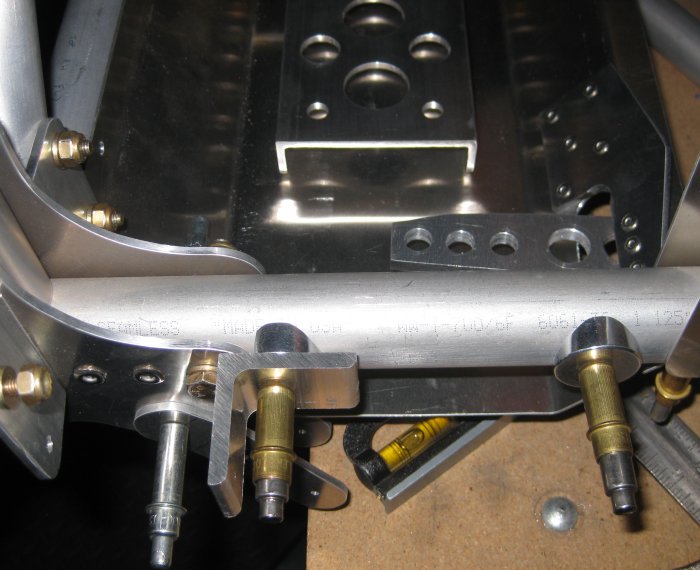
3/4 hr - Trimmed the first rudder pedal brackets to remove excess material. Filed these to round off the ends of the brackets, then belt sanded and scotchbrite-wheeled the parts. Reinstalled. Clecoed the pedal in place. Looks good. Located and drilled the holes for the other pair of brackets. Trimmed the saddle spacer for the outboard bracket location. Fit the brackets in place. Will need to get back to finishing off the drilling and profiling of the other pedals at this point.
Right rudder pedal brackets rounded off.
Left rudder pedal brackets started. That inboard one still needs a saddle, but for now there are a couple of washers between the bracket and the tube putting it in the correct position.
10/1/12 - rudder pedals
1/2 hr - back to drilling the other rudder pedals. Couple more ounces of aluminum turned into chips.
10/2/12 - rudder pedals
1/2 hr - finished off the lightening hole drilling. Only have the fastener holes left to finish, but I will do the corner shaping and edge finishing before opening up those holes.
10/4/12 - rudder pedals
1 hr - Completed the edge finishing, then corner shaping and smoothing, then the fastener holes. Got the bushings set into the lower fastener locations. Got the left-hand one for the pilot cleaned off and clecoed into place.
Looking over the front seat at the pilot's rudder pedals.
10/15/12 - rudder pedals, front seat area
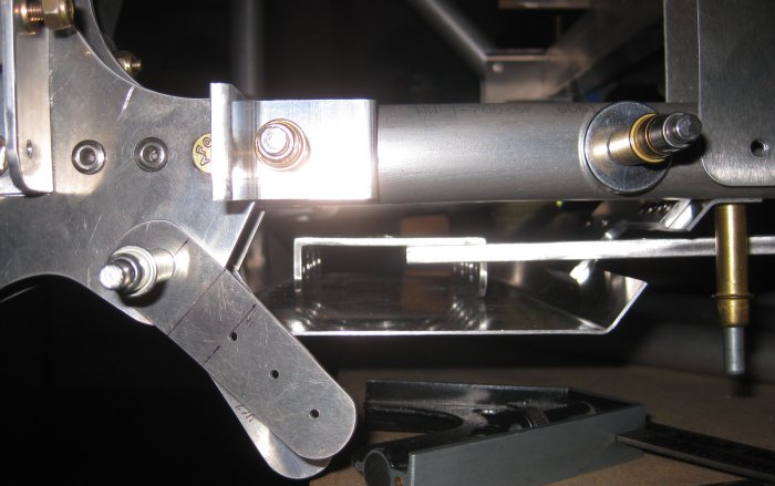
3/4 hr - after some time off, back at it. Made initial shaping cuts on the LH rudder pedal brackets with the band saw. Riveted the front seat support rails into place. Riveted the pilot foot rests into position - have to do the rivets to the outboard tubes first, then by the brake pedals, then install the diagonal tubes to get to the last rivet position. Not sure if the seat rails can be riveted after the foot rests are in, but there are some rivets on the bottom sides of the rails that look easier without the diagonal tubes or foot rests installed.
10/16/12 - rudder pedal brackets
1/2 hr - filed the final shape on the LH rudder pedal brackets, belt sanded and scotchbrite-wheeled. Installed the brackets on the fuselage frame. Tightened the aft bolts on the digonal tubes. Will need to tip the fuselage assembly off the table to get that last rivet in each of the pilot foot rests.
10/18/12 - clean-up and upper structure
1/2 hr - cleaned markings off of tubes that will no longer be disassembled. Un-clamped the structure from the table and tilted it down to install the inboard aft rivets for the pilot foot rests. Ok, those are all in. Moved the structure to the floor so the upper diagonal could be clecoed back in. Found the upper diagonal tube in the collection of tubes on the work table and got it back into position. After re-making the left side FT20, the upper diagonal pilot holes don't line up exactly. I had the feeling that the FT20 was pulling a little (a hair short), so will need to level the structure and ensure squareness. It may be that the pilot holes are a little off - better to make any adjustment now at pilot hole size. Then when drilled to final size, discrepancies like this just disappear.
10/21/12 - forward structure
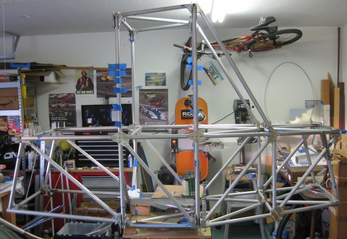
1/4 hour - after a couple days off doing the annual on the Sonex, back to this. Found a couple more rivets that could go into the forward structure - upper longerons to the engine mount cross beam, and the aft end of the upper longerons where they join the central box. So the front end is on to stay. Still trying to puzzle out the order for the diagonals - looks like if the aft part of the X goes in, then the upper structure can not be removed to install the fuselage top.
1 1/2 hour - drilled the uppermost tubes between the two main fuselage frames to final size, plus the upper ends of the FT20's to 1/4". Got all this deburred and the chips out of the tubes. One wise move here was to cover the tube clusters below with plastic bags so chips did not go between the tubes and gusset plates on the joints already permanently riveted / bolted.
10/23/12 - forward structure
1/2 hr - clecoed the lower tubes of the forward structure back into place. Because the next step there will be to fit the saddles under the U brackets at the lower aft corners of the forward structure, all these parts need to be in place anyway, plus it gets them off the work table.
10/24/12 - aft structure
1/2 hr - started fitting up the upper tubes of the structure aft of the center box. Got the upper longerons leveled, and the FT34 cross tube in place. Either I made the FT34 from the wrong diameter, or it takes spacer tubes at either end. Took a while to locate the FB30A plates, but they were in the box with the aft-of-center-box tubes and U-channel brackets.

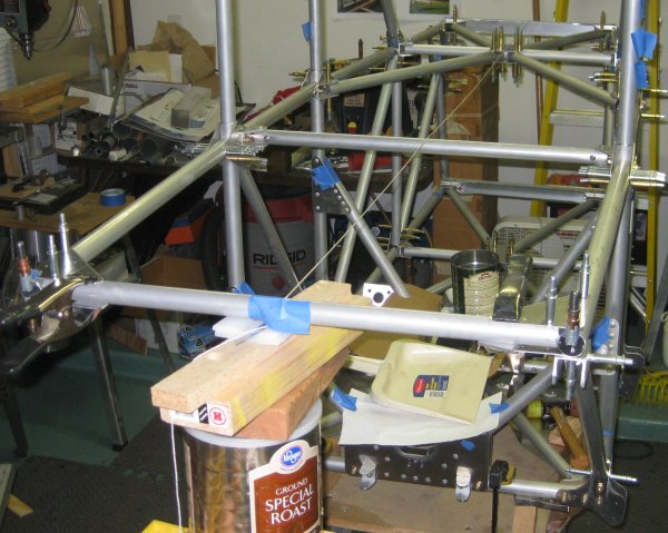
Positioned the small table with the center box clamped to it such that a stack of items on the large work table would raise the FT34 cross tube to the necessary level.

10/26/12 - aft structure
3/4 hr - after thinking about it, decided to proceed with pilot drilling the upper longerons to the center box. Checking the FT34, there are 4 other tubes called out at 1.0 dia. that interface in the same way at the aft end of the lower longerons, so this is correct. Also looked at the photos on the plans CD, and these tubes are clearly 1.0 joined via gusset plates to 1.125. The gusset plates just have a bend to them. I can keep the plates straight with small spacers between the plate and tube or with tubular spacers same as is used on some of the tubes more forward in the fuselage. Either way, I fitted the diagonal on the right side which required some fish-mouthing at the lower end to clear the bolt head on the center box structure.
Thinking on it some more, one end of the FT34 (and probably the FT35) have small u-channel brackets that are ball end-mill cut to fit 1.0 dia. tubes. So for spacers, I will need to use flat .062 here.
.125 spacers clamped under the FT34 cross tube.
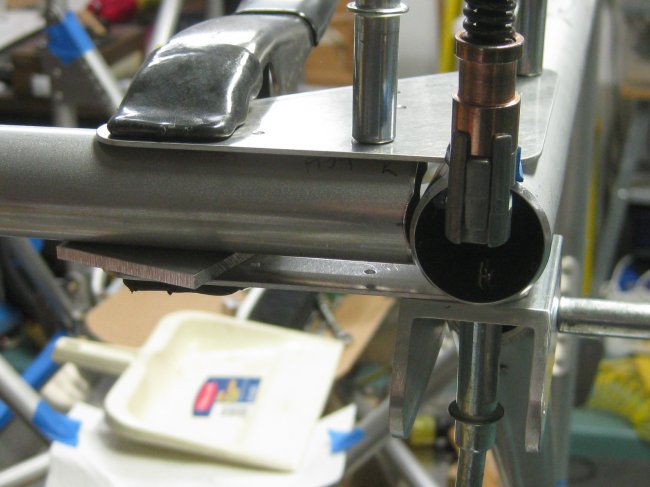
Close-up view of the temporary spacer.
10/27/12 - aft structure
After spending about half of the day at Copperstate (0645 to 1420 time away from home)...
1/2 hr - drilled some more of the upper longeron to FT34 cross-tube. Started making up a spacer between the gusset plate and the FT24 tube.
3/4 hr - started on the lower longerons and FT35 cross-tube. The lower longerons are also 1.125, but they join to the center box through U-channel that is 1.0 inside. To do this, 1.0 x .125 inserts go into the lower longerons and fit inside the U-channel. The notes on the figure say to drill these last. Not sure if that meant to drill the 1.0 to the 1.125, or if that meant to get the 1.0 insert tubes into the U-channel somehow, as the 1.0 insert tubes are not drilled. I figured, they probably have the same hole pattern as many of the rest of the tubes - holes 180 deg. apart, 10mm from the end. So I measured and marked that on the insert tubes and drilled that on the drill press. Then I clecoed the insert tubes into the U-channel brackets. That way, there are stubs to put the lower longeron tubes onto. Next, how to hang the FT35 cross tube from the upper longerons? I saw in a photo from the factory website that they put the vertical tubes on the OUTSIDE of the u-channel brackets so the brackets could be clecoed to the upper and lower longerons. They did this using what looked like .125 rod stock. Well, my brackets and tubes are drilled to #40, so I stuck some old #40 drill bits through the tubes and used the drill bits to hang the tubes on the outside of the u-channel brackets. Then it was simple to swing this whole hanging assembly - the FT35 cross tube + the lower longerons onto the 1.0 x .125 stub tubes. Now it should be fairly straightforward to drill all these parts to make the connections more solid. This fuselage is getting rather long in the shop, but I know it's less than halfway to its full length...
Lower longerons and FT35 lower cross tube in position.
Lower tube coming out of the U-bracket to the right is the aft lower longeron. This one has the 1.0 x .125 tube inserted inside.
Showing the drill bit used to hold the aft diagonal to the outside of the u-channel bracket. The tube needs to be out of the way for the clecoes inside the u-channel bracket.
Upper aft left corner showing the aft diagonal tube held to the outside of the u-channel bracket with a drill bit.
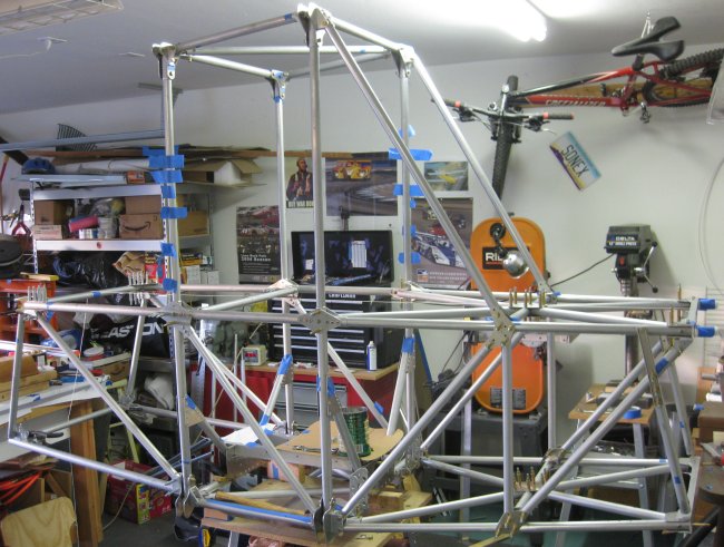
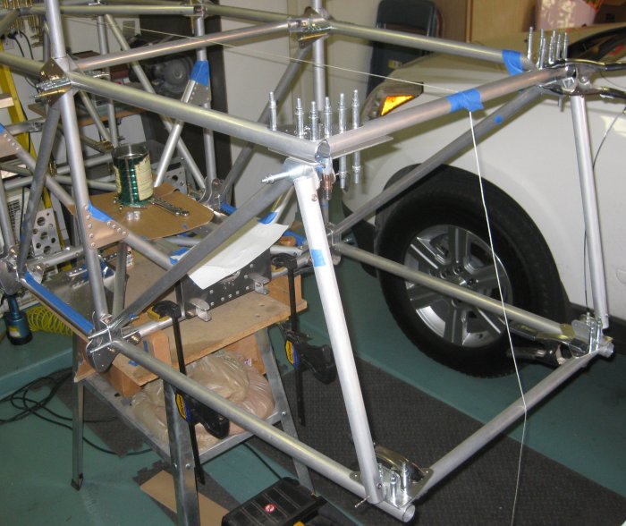
Overall right side view.
Click to join sherwoodbuilders