Sherwood Ranger - Fuselage - 9
*This web site is NOT owned or managed by G-TLAC. G-TLAC is not responsible for the content unless explicitly stated. See Disclaimer.
11/12/12 - aft section
1/2 hr - drilled lower left longeron forward end to final size, deburred, and installed the rivets. Seemed like this was one location that does not benefit from staying in clecoes only. Also drilled one of the FT29 brackets through to the small facing bracket which holds the rudder cable fairlead as well as bolts through the seat rail to join the small angle between the rails (not yet shown because I haven't made it yet).
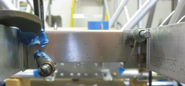
Lower aft longeron, forward end. 3 pair of rivets in that one.
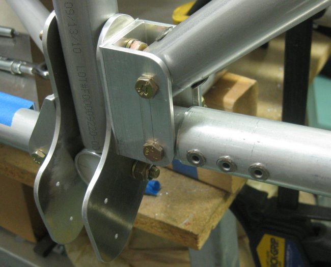
Scrap clamped to foward side of FT29 bracket. L-bracket that holds rudder cable fairlead clamped to the aft side of the FT29 bracket.
FT29 bracket, tube, and L-bracket drilled through and temporary bolt installed.
11/14/12 - aft section
3/4 hr - drilled lower RH longeron & diagonal and the upper LH aft longeron. Deburred and installed rivets in the lower longeron. Thought about rivets in the forward section, but considering what should go on before what else, I gave up trying - need those saddle parts.
11/15/12 - aft section
1/2 hr - drilled top side of seat rails to center frame. Drilled RH upper longeron to final size at forward end. Drilled the fairlead bracket on the left side to final size against the FT29 bracket, and to pilot size against the seat rail. Drilled 1 hole of the right side fairlead bracket to final size. Holes in the fairlead bracket did not line up exactly with the FT29 bracket, but they were close enough that in up-sizing the holes, the difference disappeared. It would be easier to make the fairlead brackets without the holes that mate to the FT29 brackets.
Forward end of RH upper aft longeron drilled to final size.
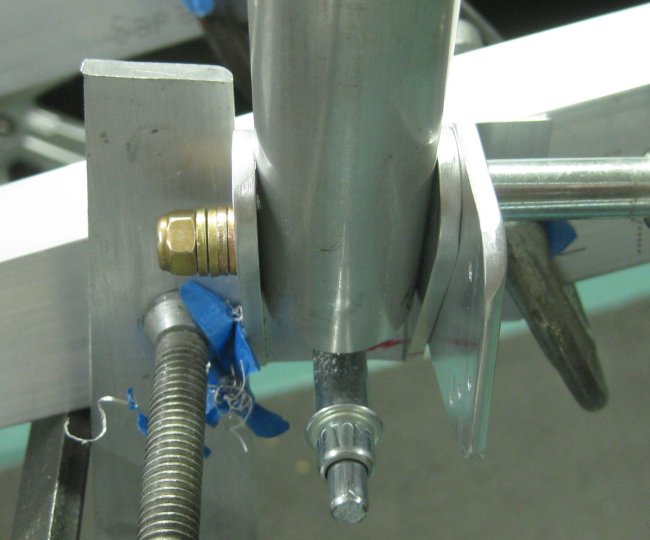
Fairlead bracket, lower end of LH FT29.
11/16/12 - aft section
1 hr - got a few more holes drilled. Drilled the RH lower FT29 bracket and the fairlead bracket drilled to final size. For the fairlead bracket, drilled through the bracket into the seat rail. On the left side, I had left these through-seat-rail holes at pilot size in order to drill the between-seat-rails bracket to these same hole locations at the same time. But I forgot that on the right side, so that between-seat-rails bracket will have to get its initial drilling at final size. (Still need to make those between-seat-rails bracket parts.)
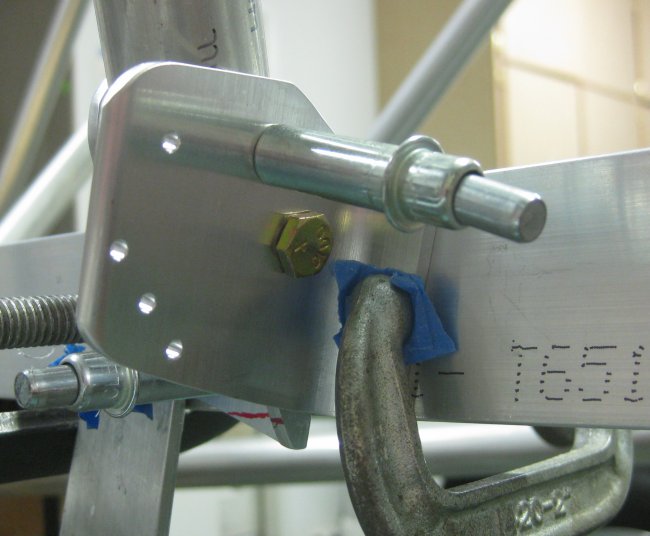
Fairlead bracket, lower end of RH FT29 - final size with bolts.
11/17/12 - aft section
1/3 hr - disassembled the seat rails from the structure in order to access the lower seat rail brackets at the aft side of the aft central frame. Also pulled out the lower diagonal tubes (FT36?) for access to these brackets.
11/18/12 - aft section
3/4 hr - drilled the lower seat rail brackets to the central frame. Deburred this, put the rails back in place, then decided I could up-drill the brackets and rails separately on the bottom-side hole in the rails. Did that, deburred, clecoed the rails back in. Made up the brackets to go between the rails. Still need to make up the larger L-section cross piece that goes between the rails.
11/19/12 - research
No working with hardware today. Got the engine build guide from Raven. This converts the 993cc Suzuki / Geo 3-cylinder car engine for aircraft use. In a quick review of the manual, the big parts of this are preparing the car's wiring harness and adding the belt-driven prop-speed-reduction-unit. Another major aspect is reducing weight. Seems like a very well thought-out and tested engine package.
11/20/12 - aft section
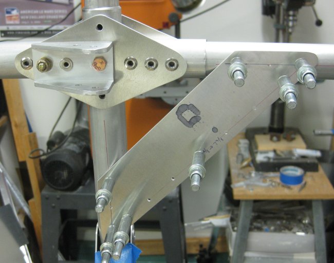
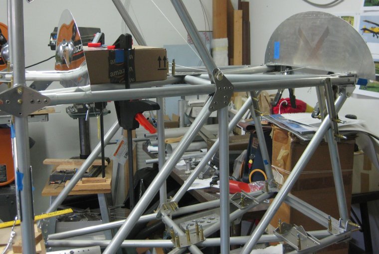
3/4 hr - Made up the L-section to go between the seat rails at the FT29 brackets. Got the right-side L-section attach bracket drilled to the rail and pilot drilled to the L-section. These parts are not in the photos provided with the plans - so I will take some. It took a while to interpret the drawing to figure out what is needed here.
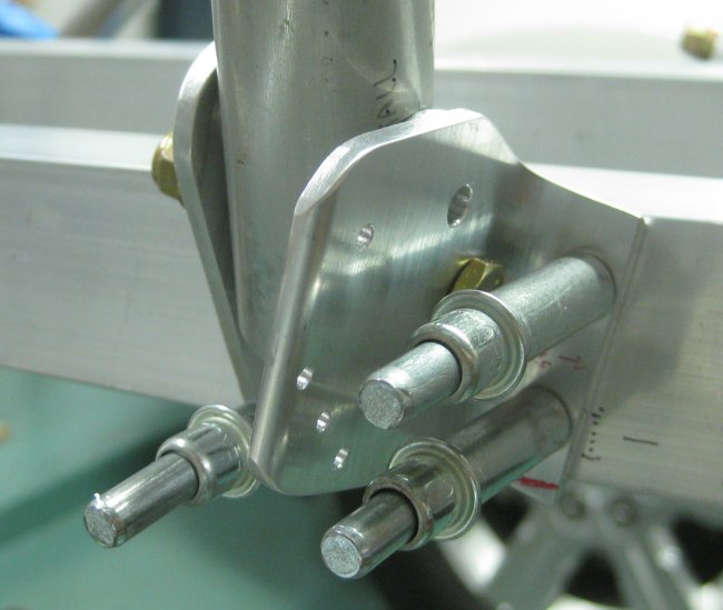
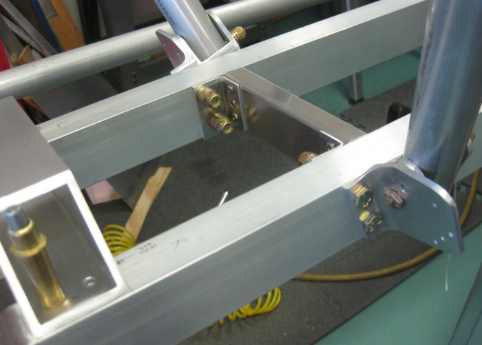
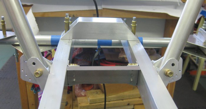
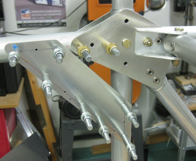
Cross brace, looking from forward right towards aft left.
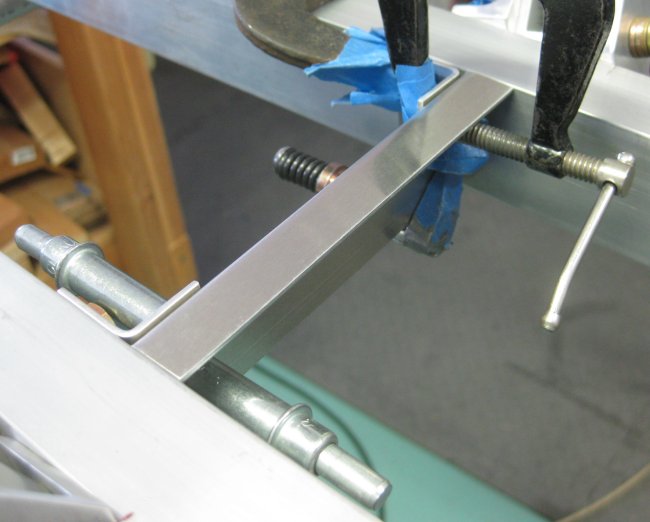
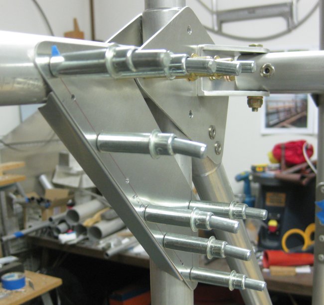
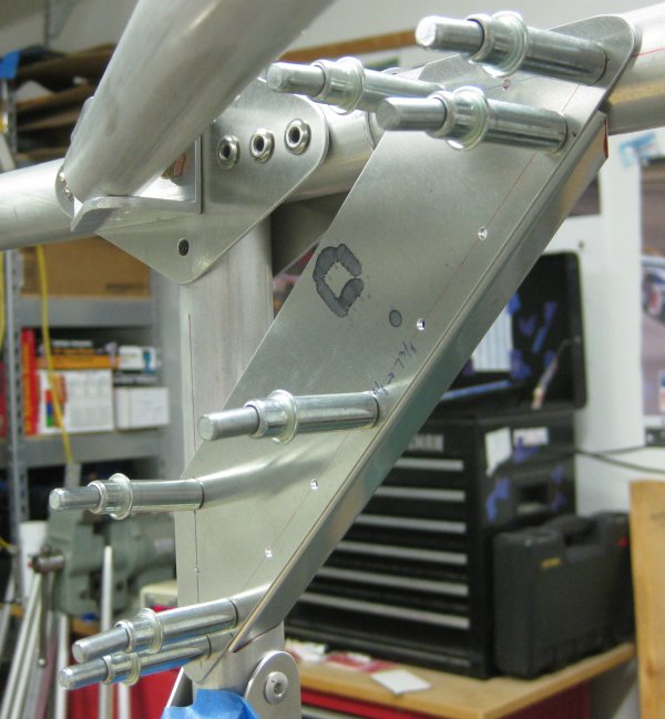
Cross brace, looking from above aft.
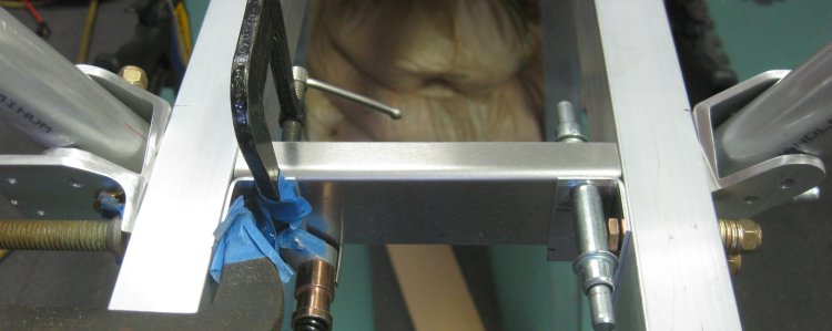
Cross brace, looking from directly aft. The cross beam does not go to the bottom of the seat rails - this is for clearance to the elevator idler pushrod.
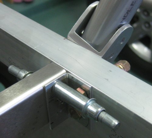
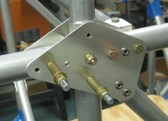
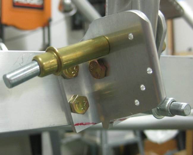
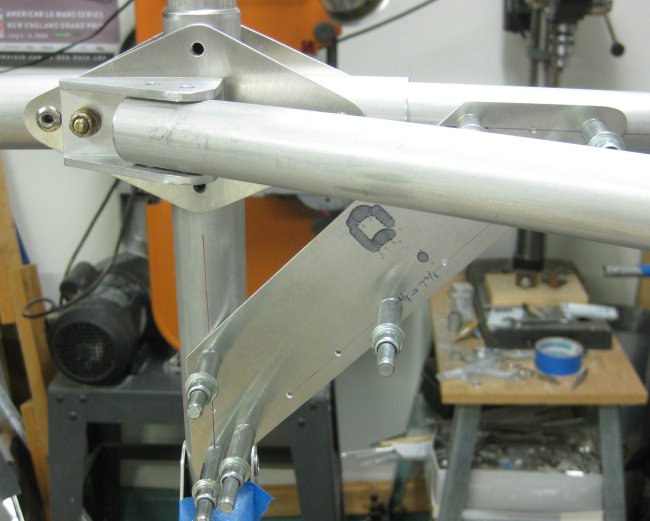
Looking at right side FT29 bracket. The rudder cable fairlead bracket was removed while drilling through the seat rail into the cross beam attach bracket.
11/21/12 - aft section
1/2 hr - drilled the LH cross-brace bracket to the seat rail. Drilled the cross brace to the LH cross brace bracket. When drilling through the rudder cable fairlead bracket through the seat rail and out the other side for the cross brace bracket using the 12" #40 drill bit, the drill bit flexed out the far side so the hole was offset. To get the hole going straight through again, I pulled off the seat rail with the cross brace bracket, the fairlead bracket, and the FT29 tube bracket. I drilled through this assembly on the drill press. This brought the holes back in line, so the bolts through the seat rail and these brackets fit well. This assembly, though it doesn't look very complicated or like a whole lot of parts is fairly involved to get all fitted and drilled.
11/22/12 - aft section
3/4 hr - drilled the lower FT29 brackets to final size to the seat rails. Trimmed the corner of each bracket that protruded below the seat rail as unnecessary material. Deburred and riveted the FT29 brackets to the seat rails, as everything is at final size, and I don't see this getting in the way of anything else. Drilled the cross-brace to its attach brackets to final size. Trimmed the cross-brace attach brackets to remove the lower inboard corner. Deburred and riveted the cross-brace attach brackets to the cross brace. Put the bolts through the fairlead brackets and seat rails temporarily to hold the cross-brace in place.
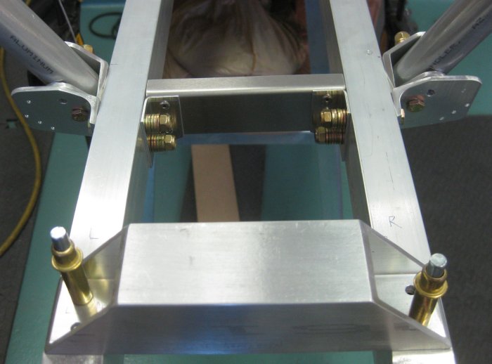
View from aft looking forwards. Note bolts have excess of washers for temporary installation. Bolts are correct length, but big stack of washers avoids engaging the lock on the nuts.
View from right rear.
View from forwards looking aft.
11/23/12 - aft section
1/2 hr - Drilled the upper end of the RH FT29 to final size. This required removing the upper longeron for drill access to the upper side holes. Might have been able to do this with the right angle drill. Note - might need to rivet the FT29 before the other tubes in this area, at least before the upper longeron.
1/2 hr - Drilled the gusset plates at each end of the upper cross tube (FT34) to final size, top and bottom. Deburred. Also finished drilling the upper end of the LH FT29 to final size.
11/24/12 - aft section
1/2 hr - Put rivets into the lower side of the upper cross tube at the gusset plates on each end. Drilled the upper end of the side diagonals to final size and installed bolts through these. Started layout of throttle support brackets. These are not defined for thickness or size (that I could find), so scaling from the assembly drawing, I made them 1.875" wide from .040 material.
11/25/12 - aft section
1/2 hr - re-installed the FT36 tubes in order to drill the last of what can be drilled to final size at this point (prior to installation of the aft longerons). Cut out the throttle support plates from .040. In the photos, these may have been thinner, but just holding them in place the .040 seems a little flexible. Though the loads are not very large - these parts could easily be substantially stiffened up with the addition of a little .025 angle.
11/26/12 - aft section
3/4 hr - checked location for rear seat bottom attach bolts. Decided 8" back from forward end of the seat rail and 8" back from that point would work. Marked these 1/2" down on the rails and drilled to #12. Drilled the forward end of the FT36 tubes to final size and installed temporary bolts through the u-channel brackets.
11/28/12 - aft section
1/2 hr - drilled the bottom side of the aft end of the FT36 tubes and the lower cross-tube to final size. Did not drill the aft longerons because the tail support tubes also go inside the aft longerons (aft-aft-longerons?). Marked off and cut out stiffening angle blanks for the throttle mounting plates.
11/29/12 - aft section
1/3 hr - bent up the stiffening angles for the throttle mounting plates. Trimmed the shorter one. Marked rivet hole locations and drilled to pilot size. The stiffening angle is 0.5" x 0.5" x .025. This is not called out in the prints, but the thickness of the throttle support plates was not either.
11/30/12 - aft section
1/2 hr - marked the fuselage tubes for the throttle mounting plates. Drilled the aft plate into position. Marked and drilled the forward plate for the gusset. Drilled this plate into position on the fuselage tubes.
Aft plate in position.
Aft plate, showing the riveted-on stiffening flange along the long side.
Forward plate - good to get the throttle mount plate installed before the diagonal tube is riveted in.
Since the diagonal tube is not riveted in, swing it out of the way for access. Forward plate is longer than the aft plate by about 25mm to clear the short spacer/doubler tube on the upper longeron.
Showing the stiffening flange to be riveted on.
Showing both plate locations.
12/2/12 - forward section
1/2 hr - pulled some rivets on the J5 and J5A joints in the forward section. Trying to figure out what order to do things so I don't get stuck with some rivets that are impossible to pull.
12/3/12 - forward section
1/2 hr - pulled some rivets on the J1 joints in the forward section.
12/4/12 - forward section
3/4 hr - pulled rivets on the J1A and J13 joints. Used bolts on the J5/J5A at the FT26 tube - tightened those bolts. Only did the forward portion of J13 - left the FT28B's loose as well as the bottom plate of J13. Still need to be able to move those FT28B's around. Rechecked the hole position markings on the upper aft longeron tubes. Set up the drill press to be able to drill the aft longerons. Plan is to drill at the forward insert location, push the insert into the tube the correct distance, then drill at the aft insert location and add that insert. That way, the forward insert will not have to push past a bunch of pilot-drilled hole locations.
12/5/12 - aft section
3/4 hr - drilled the upper right aft longeron per the plan. Pilot drilled at the forward insert location first, pressed the insert up into the tube, drilled that through to #40, inserted clecoes as a marker that the insert is in there. Insert probably would not move with the holes drilled through. Then slid it into position on the upper aft corner of the mid fuselage. Lined it up and drilled through.
12/8/12 - aft section
3/4 hr - drilled the upper left aft longeron, same steps as above to get the inserts in as needed. Slid it into position on the upper aft cornern of the mid fuselage and drilled through a few of the hole locations. Then made up a spacer part from a scrap of .125 (strip) to represent the forward stabilizer spar and clecoed that on - the two longerons definitely pull in with a slight curvature to them. Then clecoed on the aft seat belt attach plate at the aft h-stab spar location.
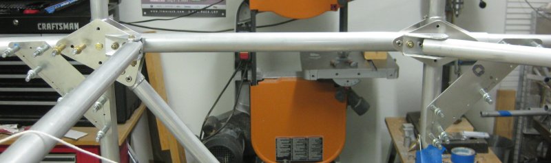
Both upper aft longerons in position.
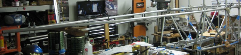
View forward looking aft. Trying to show the curvature of the aft portion of the longerons.
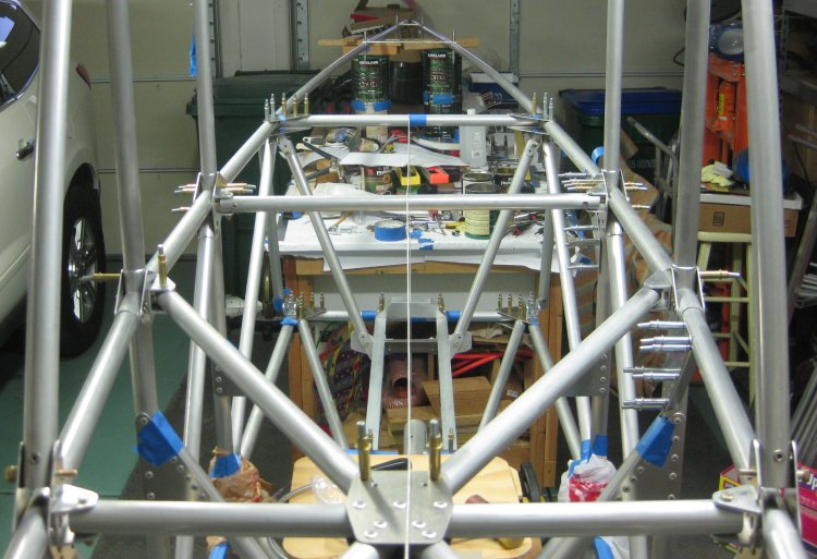
Closer view of the aft seat belt attach plate and temporary spacer across the h-stab spar attach points. This draws the aft longerons into a curve.
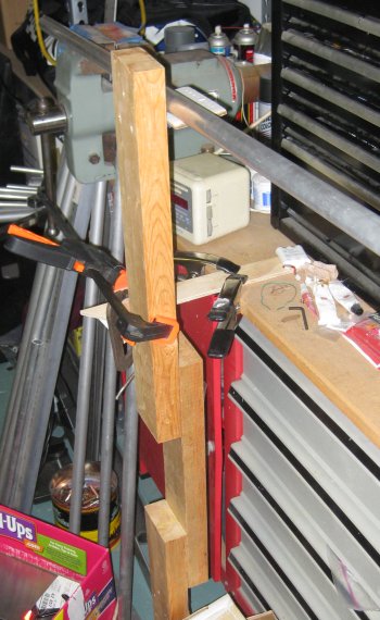
Temporary tube support clamped to workbench.
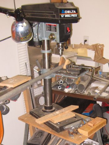
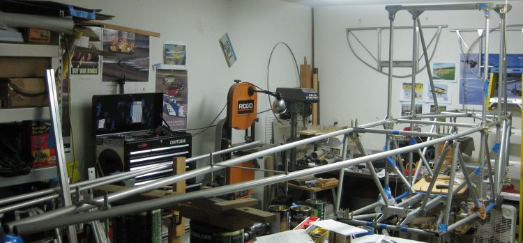
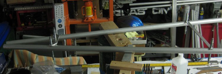
Moved the drill press out away from the wall so these long tubes could pass in front of the band saw.
12/9/12 - aft section
1/3 hr - checked the hole locations on the lower aft longerons and drilled one of them. Forgot to push the insert in before drilling the most aft holes, but I can get a file into the end of the tube to smooth off the insides of the most aft holes to get the insert past them. My guess is this insert is to support the cables for the h-stab.
12/10/12 - aft section
1/3 hr - Installed the insert into the first lower aft longeron. Drilled the second one and installed the insert in that one as well.
12/11/12 - forward section
3/4 hr - laid out and mocked up the upper firewall. Had enlarged the installation figure on a copier, then took some measurements of some known items shown there to determine the scale. Then applied the scale to other dimensions to start creating a mock up. I'm considering fabricating the top of the fuselage with sheet metal rather than the fiberglass molding sold from the factory. I think the top of the fuselage looks a little flat, and the shapes of the passenger openings could be more rounded for a more classic look. By making up some bulkheads and wrapping that with flat sheet, I think I can get the shape I have in mind.
Cut out an 8" x 25 1/2" piece from a (polished!) scrap from the Sonex project. I had originally calculated the ellipse at 6 1/2" high, but decided another inch might look better. The 1 1/2" extra was to allow the mock-up to sit flat to the 1 1/2" firewall cross beam. Eyeballed a quarter of an ellipse on here, measured points every 1/2" up, and transferred them to the other side of the part to give half of an eyeballed ellipse. Decided for all this, I should look up the mathematical formula for an ellipse - that way when I scale it to another width/height farther back on the airframe, I won't end up with two different lumpy bulkheads.
12/12/12 - forward section
1/2 hr - looked up the formula for an ellipse. Made up an Excel spreadsheet to calculate ellipse dimensions. Calculated the points for 25 1/2" wide x 7 1/2" high. The 25.5 is the scaled dimension for the firewall width at the upper fuselage forward cross beam. 7 1/2" high is my estimate of the height at this point - though I'm making this maybe 1 1/2" higher than the fiberglass molding to give the top of the fuselage a more rounded look, set the pilot down a little deeper in the machine, and possibly provide for a little more fuel volume since the tank sits on top of the forward fuselage structure under the fuselage top skin.
12/13/12 - forward section
3/4 hr - plotted the points for the calculated ellipse on the opposite side of the 8" x 25.5" blank. Cut this out. Filed the edges. Scotchbrited the edges. Clamped the part to the firewall cross beam.
12/14/12 - forward section
3/4 hr - drilled some angle parts off of the leftover Sonex assembly to free up more scrap. Calculated and plotted an ellipse at the same 7 1/2" height as at the firewall, but 29" wide. This will go at a station 31 1/2" back from the firewall. This is where I estimate the front-seater's panel would be. Cut out the 29" half-ellipse from the scrap material. Just to see, did some sample calculations on various sizes of fuel tank. I believe something on the order of 10 gallons would be sufficient for the 60-80hp engines I'm considering. This airplane isn't for extended cross-countries. About the longest trip I expect to make is 47nm from the home airport to another airport that does monthly pancake breakfasts and two larger fly-ins each year. Farther than that, may as well take advantage of the folding wings and use a trailer with all-weather capability... Anyway, 10 gallons easily fits with a good 9-10" to the firewall. Though I haven't figured out how much of an obstacle the cable cross brace between the FT20's might be.
1/2 hr - put some string in place to represent the cables at the FT20 tubes. Marked cutouts in the bulkhead mockup and checked relative to the fuselage tubes. Decided not to cut the mockup bulkhead right now.
12/15/12 - forward section
1/4 hr - reconsidered the height to mount the elliptical bulkheads. Noted that at the firewall, I had clamped it on such that it was 7.5" from the top of the firewall to the top of the fuselage forward cross-beam. This is ~.25" above the level of the upper longerons. So the bulkhead at the front-seater's instrument panel location should be set such that its top is 7 3/4" above the top of the tubes. So adjusted the marking I had made last night and cut the bulkhead mockup so its top is 7 3/4" above the upper longeron tubes.
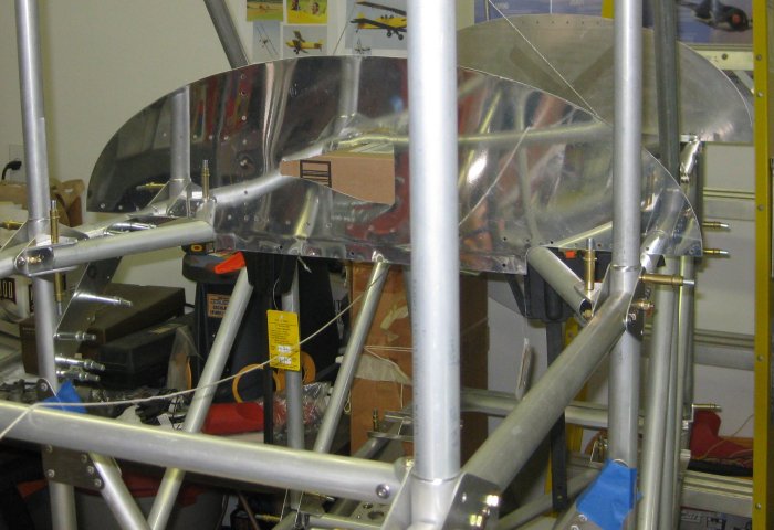
View of front-seat instrument panel bulkhead mockup. NACA vent is not part of the plan...
Looking over the panel towards the firewall.
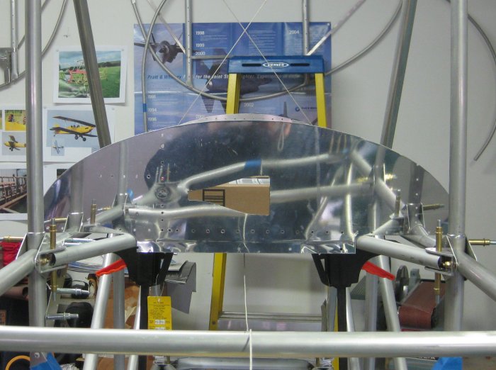
Took this photo from a little lower down - trying to show the X of cables between the FT20 tubes that intrudes into prime fuel tank volume. The factory tank is cutoff at angles to remain forward of these cables. The factory tank also has a 3-sided "well" on the right side between the fuselage diagonal tubes to provide a little more volume. I am currently studying available volume in a flat-bottomed tank because it might be simpler to build, but to get the desired volume and avoid the cables I may end up going with well(s) between the fuselage tubes.
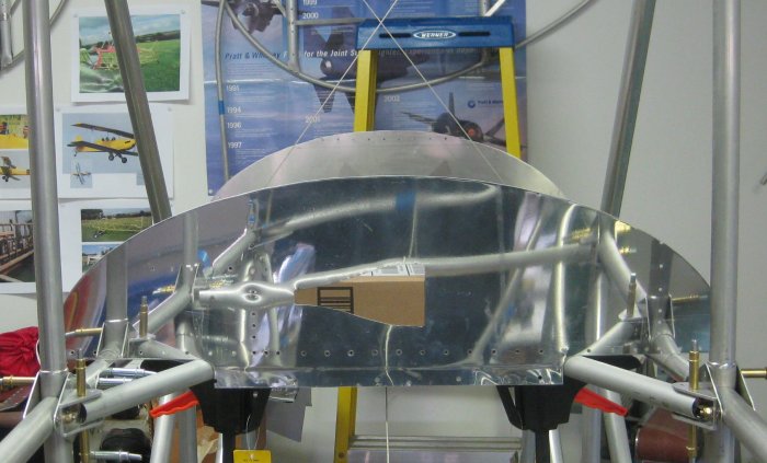
View from the right side. There's 15+ gallons of volume up there, and I would prefer around 10 gallons in a flat-bottomed tank.
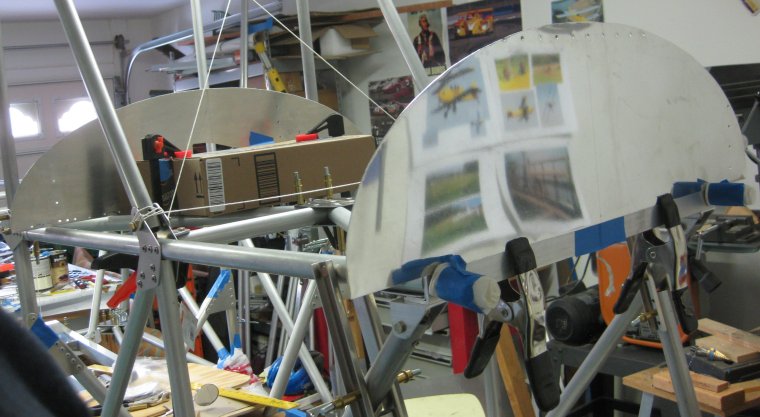
View from the front. Yes, I had polished that old Sonex assembly that I ended up having to scrap out.
12/19/12 - panels/fuselage top
1/2 hr - a few days off, but cut out another bulkhead mockup at the pilot's panel station. The panel is actually quite large size in the form of a bulkhead all the way across. Considered what to do for behind the pilot - need to study the drawings some more.
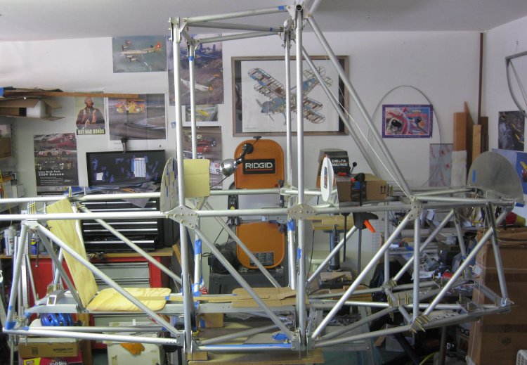
Side view - also did some work changing things on the garage walls. Got a vintage 1977 cutaway poster of a Christen Eagle II at the local EAA chapter holiday dinner in a gift exchange. Nice enough to be worth buying a frame. Also hung up some old aircraft calendar pages.
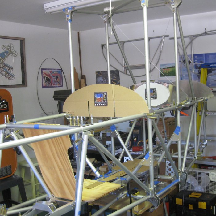
Mocked up an oval instrument panel insert for the front-seater's panel. These panels really are quite generous in size done as a bulkhead like this. The factory molded fiberglass fuselage top is angled across the panel - splits it up into 3 smaller flat areas to mount things. Probably will not go with the dual MGL all-in-one displays. Might use something like their E1 for the engine, and some steam gauges in the back-seater's (pilot's) panel.
12/27/12 - forward section
1.5 hr - went over to Industrial Metal Supply for 1x1x.062 angle and .018" SST. The SST is for the firewall and the angle will form the fuselage top skin attach structure as well as the point where the fabric attaches along the forward fuselage sides. Per the prints, it appears the fabric is bonded to the fiberglass fuselage top. What I'm doing will be a little more traditional with the sheet metal for the fuselage top - and hard to beat the cost. The angle was ~$8, and I have the rest of the material for the bulkheads and top skins. May need to buy an additional bag of rivets, some nutplates and screws. Also will need some 5/16" thin-walled tube for the cockpit surrounds. Saw on a Hatz they rivet the tube inside the lip of the cockpit openings to provide some stiffness, then slice some fuel or water line to wrap around that to bulk it up a bit, then some pipe insulation over that to provide a nice cushion, then wrap that with vinyl or leather to finish off the cockpit openings.
12/28/12 - forward section
1/2 hr - front seater's instrument panel bulkhead - thought I had some .032" in an old Sonex flap. Cut a section from it in order to mark the outline of the bulkhead + 1/2" to allow for a flange. Should have measured better before cutting - it was .025". Probably would work, but I might want to make a pretty sizable cutout for an instrument insert, so would prefer .032". Have a fairly good-sized piece of .032" to work with, so outlined the bulkhead on that. Found a washer with a cross section slightly > 0.5" wide - clamp the bulkhead pattern to the sheet, and using the washer as a spacer for the pen, outlined the part to be cut - a little more than 1/2" larger than the pattern.
12/29/12 - forward section
Went to the Home Depot aircraft tooling supply for some MDF - floor underlayment material seemed to be about the right density to make some form blocks for hammering flanges onto these bulkheads.
1/4 hr - cut out the front-seater's panel bulkhead blank from .032 and filed the edges smooth.
12/30/12 - mid fuselage
1/4 hr - cut out the aft-seater's panel bulkhead blank from .032 and filed the edges smooth.
1/1/13 - fuselage top
1 hr - cut down the MDF to smaller rectangles on the table saw. Miscounted, and cut 1 set too many. Started marking form blocks and block backing parts on the cut down rectangles. Have to plan out the flute and fastener locations now, before cutting out the blocks.
1/2 hr - traced the patterns onto the form blocks and started laying out the flute locations. Not completely sure on this, but estimating the quantity and spacing of the flute locations based on what I recall of the Sonex form blocks. Oh, and I didn't make an extra set of form block blanks - will need the 4th set for the angled bulkheads that form the top of the seat back for each of the seats.
1/4/13 - tail channel
1/2 hr - got a HF 30" brake to replace the 18" which has seen better days. The 18 was overloaded earlier in the Sherwood project, and was loose. Something like that could go at any point. So the 30 was on sale + a coupon. Problem - it has some extra material on one of the hinges that prevents it bending far enough past 90 degrees to put enough bend on the part. But it worked well enough that I can use the piece of channel that I had forgot to make for the top of the rudder (need 2, I had made 1). Also need to bend up a channel to mount the bottom of the front seater's panel.
1/5/13 - form blocks
1/2 hr - got 2 of the backing blocks cut and one of the form blocks. For the form block, drill the flute locations first with a 1/2" dia. drill, then cut the perimeter. Realized I may need yet one more form block because the seat back behind the aft seat is narrower than the one at the forward seat. So that's 5 different form blocks total: Firewall, instrument panels, forward seat back, aft seat back, and aft close-out bulkhead.
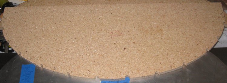
Forming block
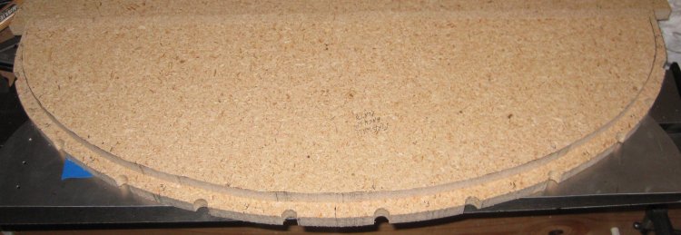
With backing plate
Click to join sherwoodbuilders