Sherwood Ranger - Empennage - 1
*This web site is NOT owned or managed by G-TLAC. G-TLAC is not responsible for the content unless explicitly stated. See Disclaimer.
5/14/11 - Placeholder for start of empennage construction. Control surfaces?
11/25/11 - Start grid layout
1 hr - The curved portions of the tail surfaces are laid out in half scale on sheet 5. Due to my printing limitation, I took a bunch of screen shots and pasted small segments of sheet 5 onto 12 8.5x11" pages. I have no idea what scale that turns out to be, but it doesn't matter much because the sheet includes a 30mm x 30mm grid used to lay out the parts. So I cleared off the work table, rolled out some white paper that the kids had for drawing on, and laid out the grid. No parts drawn on there yet, but there's a start.
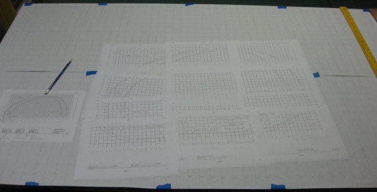
Grid laid out on the table.
1/2 hr - trimmed edges of the multiple printed pages and taped them together to form one large sheet 5, and transferred the curves from the plans sheet to the full-size grid on the table.
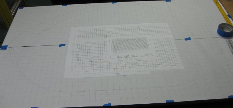
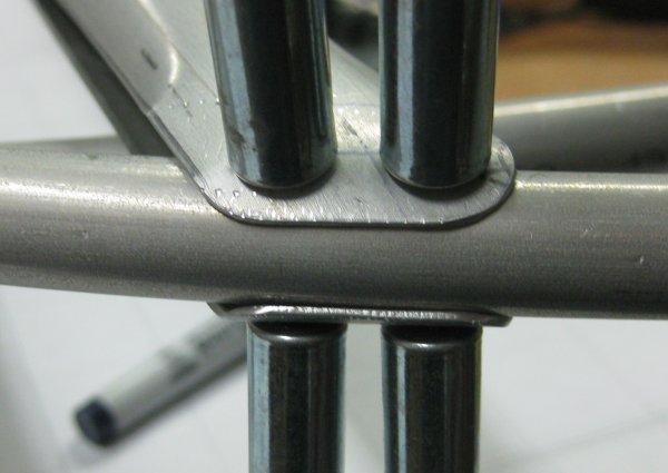
Grid with tail surface tubes laid out.
11/27/11 - Cut radius block
1/2 hr - Cut the two (why didn't I order spares?) lengths of 1/2" dia. control surface trailing edge - one 12-foot length cut right in the center, leaving 2 elevator trailing edges with ~6" to spare on each one, and cut ~3-foot length off the other. The long piece is the rudder trailing edge, the short piece is for practice. Tried bending a little of the practice piece in the ~3-inch radius bending block I had screwed to the bench. Big problem - the bend takes off in 3-d - as in, the tube doesn't lay flat to the table.
Sometime during the day, watched the Nieuport in 9 minutes video on the Airdrome Aeroplanes site. This showed me a key idea for keeping bends flat - large radius blocks!
1/2 hr - found a scrap of MDF, and using a 24" dia circular (kids) table, drew a 12" radius circle on that and cut it out. Screwed it to the table. Bent the other half of the practice piece on there, and got ~16.5" radius once the tube sprung-back. Leave it at that. Time to think.
11/28/11 - Trailing edge tubes
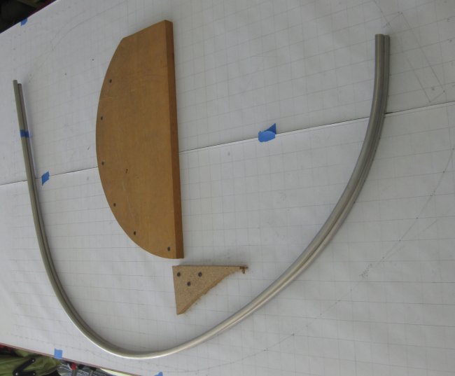
3/4 hr - with the 16.5" result / the 12" radius form is a ratio of 1.375 to 1. So, looking at the plotted out trailing edge curves, saw that portions of both run in the ~360mm radius range (14.2"). So 14.2 / 1.375 = 10.3. Found another board. Drew a 10.3 radius on that using an old drafting compass, cut the curve out on the band saw, lightly sanded the edges and screwed it to the table. Only large portion of the table left is right in the middle of the plotted page - no problem. Took the practice piece, tightened the 16.5" radius on the new block, and it then fit reasonably well on the plotted curves in the 360mm radius range. Now's the big step - starting with the elevator trailing edge, because if that gets screwed up, it might cost a little less to replace a 6-foot length and started the curve on the new 10.3 radius bending block. So far, so good. Carefully working around the curve, checking the drawn-out line often, I worked an acceptable trailing edge shape. Doesn't match the plotted line perfectly, but it's not wavy in-and-out, and the complete bent tube sits flat on the table. Looks like I might have avoided unnecessary trim drag on one elevator. Now, to duplicate that. Slowly working around from one end again, comparing the 2nd tube to both the plotted line and the first tube. Got the two to within ~1/8" of each other. Better than I thought.
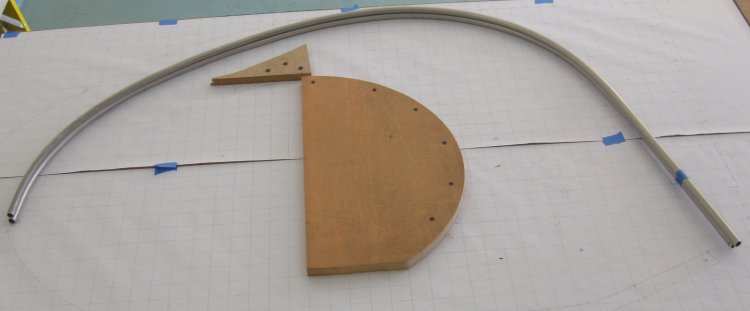
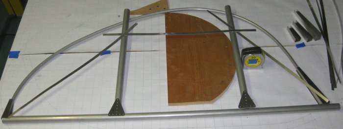
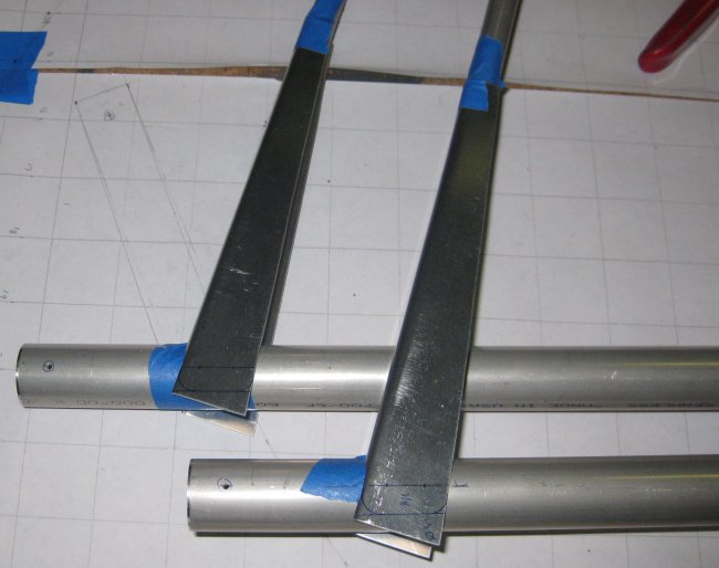
Both elevator trailing edge tubes and the radius block.
11/29/11 - Review tail chapter
1/2 hr - read through the tail build chapter. Decide it's possible to build elevators with the parts I have. Figured out way to make trim tab removeable. As shown, I don't see how to install the hinge pin after it is covered. I will probably use a trick from the Sonex gear leg covers - remove 2 hinge lugs in the center from one side of the hinge, and 1 lug from the other side of the hinge. This leaves enough opening in the middle of the hinge to install the pins from the center out. Then just have some safety wire holes pre-drilled thru the hinge and the part that it rivets to for securing the pins with a small loop of safety wire. Though this isn't absolutely necessary, as the pins can only back out into each other, and won't actually leave the airplane.
1/4 hr - bend rudder tube. This went pretty quick. Not perfectly flat, but not 3-d enough that I'm going to fuss with it too much. With very little force it can be held flat to the table. When fastened to the spar and ribs it should pull flat ok.
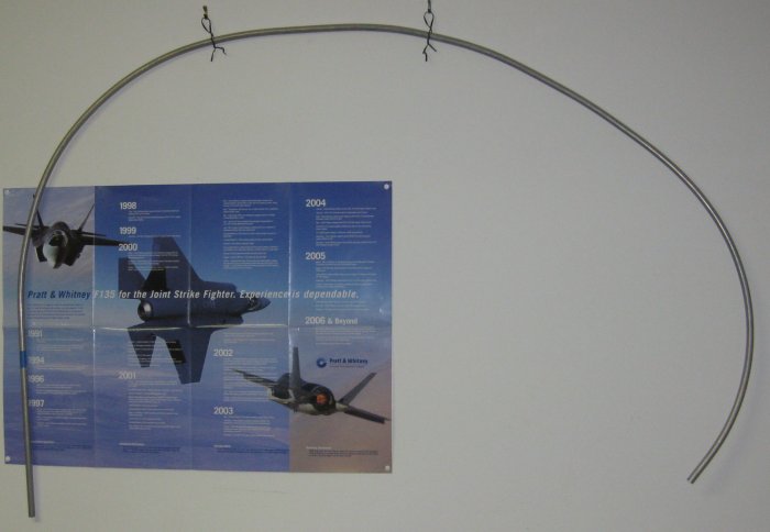
Rudder trailing edge hung up on the wall.
11/30/11 - Mark elevator spars
1 hr - also includes marking the h-stab trailing edge tubes (that are hinged to the elevators).
12/1/11 - Drill h-stab + elevator tubes
1/4 hr - drilled 3 of the 4 tubes marked yesterday.
12/2/11 - Drill h-stab tube, locate parts
1/2 hr - drill the 4th tube. Cut elevator trailing edge tubes to length. Locate the rib tubes, the trailing edge inboard- and outboard-edge channel parts (tapered channels to join the 1" leading edge tube to the 1/2" trailing edge tube), and the tail flat gusset parts. One of the ribs was not with the others, so will need to find that or make another.
That's about it for elevator parts. Whichever side gets the trim tab has a few more.
12/3/11 - Drill elevator tube, test fit
1/4 hr - drilled tube to 1/2" at the tip, where the trailing edge tube inserts through. The unibit does not quite make the hole large enough. Had to file it a little. Putting the trailing edge tube through, the other end is maybe 4-5" from meeting up with the spar tube at the inboard end. May need to bend the trailing edge some to make it meet up.
12/4/11 - Fit elevator trailing edges
1/2 hr - turned the elevator spar tube around - trailing edge is closer to meeting up at the inboard end, maybe 2-3" separation. Drilled the spar tube to 1/2" for the other elevator to see where that one came out, and it's about the same. So bent both trailing edge tubes pretty much the same to get the inboard ends to meet up. Started fitting the tip bracket. Decided I need to re-make it a little wider so it would look more like the picture. Instead of a 1/2" wide U at the small end and 1" wide U at the big end, will make with 1 1/4" wide U at the big end. That way the spar tube will sit farther down into it and there will be more material to wrap around the spar tube.
12/5/11 - Elevator TE tip gussets
3/4 hr - Re-made the tip gussets, then cut the profiles to wrap around the spar tubes. Drilled the outboard ends of the tubes into position. At first, I thought 3 little rivets on each would not be stable enough, but the TE tube itself passes through the spar tube, then when the ribs are added, there will be many more rivets stabilizing the structure.
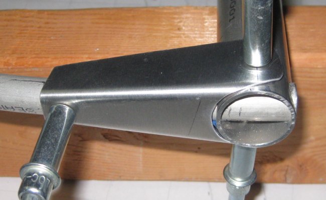
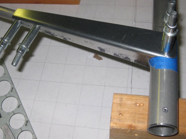
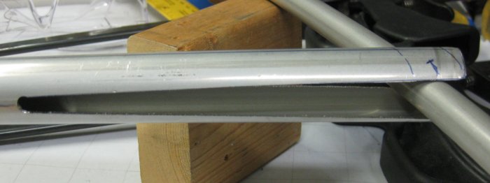
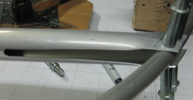
End view, reworked elevator tip bracket.
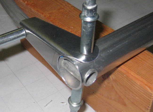
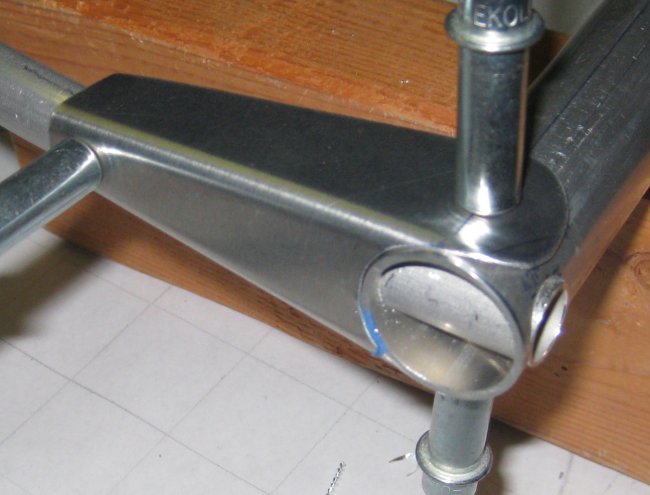
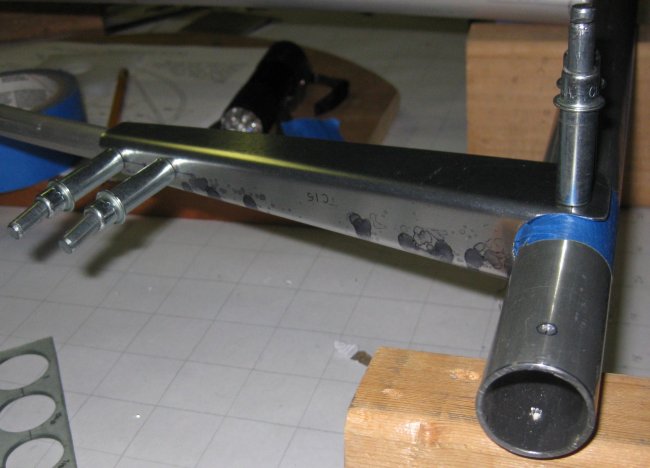
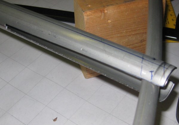
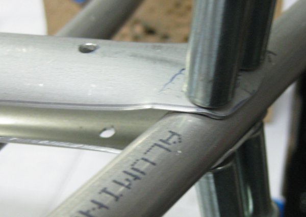
View of the bracket on the other elevator. I got a little closer fit on the cutout for the spar tube on this one.
12/6/11 - Elevator TE root gussets
1/2 hr - I thought I might have to re-make these after seeing how the others fit, but making a 1" deep cutout for the spar tube, these channel pieces fit pretty well. Marked them for trimming. I'm starting to see how these parts work - part is trimmed to final size in place. Note - the two of these for the elevators are thicker material than the one for the rudder.
Plans don't dimension the shape marked to trim here on the ends of the gusset parts. I laid out the rivet holes 1/2" apart with equal ~5/16" edge distance to each side and the flange beyond the rivet holes at 3/8" wide - TLAR (That Looks About Right).
12/7/11 - Elevator TE root gussets
1/2 hr - trim the root gusset ends to shape, file the trimmed ends, scotchbrite. Center punch the hole locations, pilot drill the holes on the gussets off the assembly. Put the gussets into place on the assembly and drill through the tubes. Hammered the ends of the gussets around the spar tube - probably will want to bend these rounded ends in a little tighter.
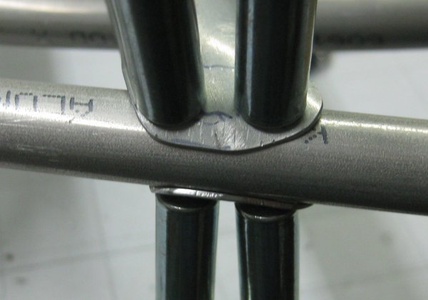
The prints don't show the spacing of those rivets up the trailing edge tube, so I put the first one 1/4" in from the edge, and the 2nd one 1" farther in. I may put another rivet closer to the spar tube just to stabilize the trailing edge tube segment that is inside the gusset up close to the spar tube.
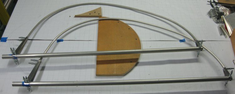
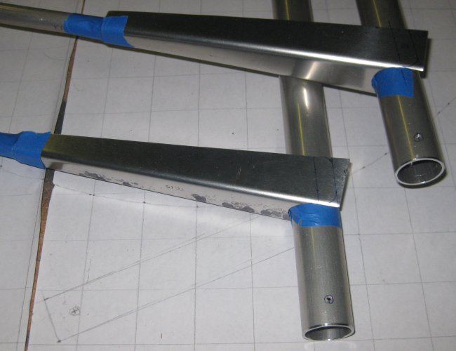
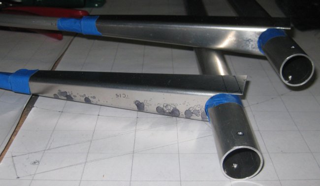
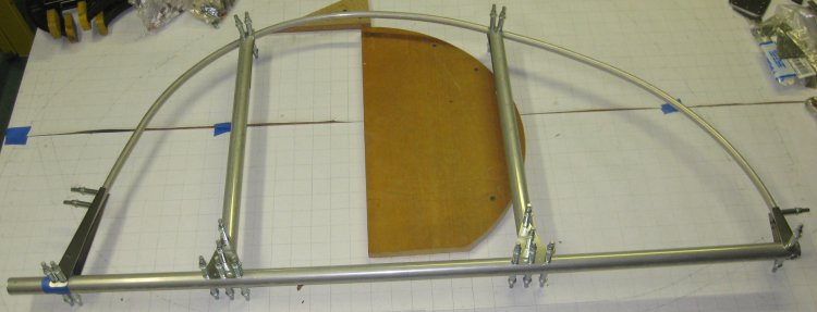
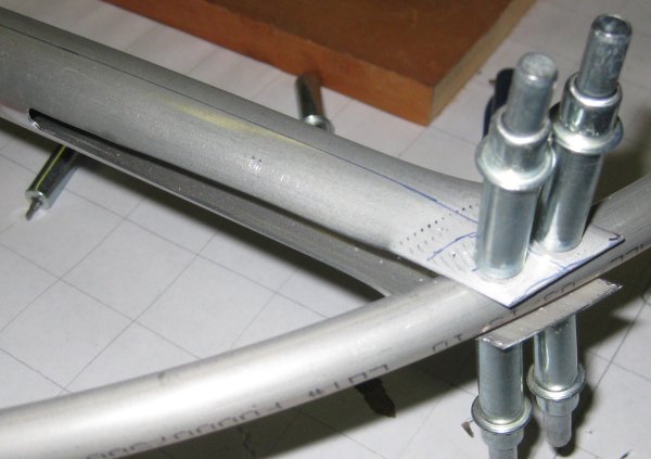
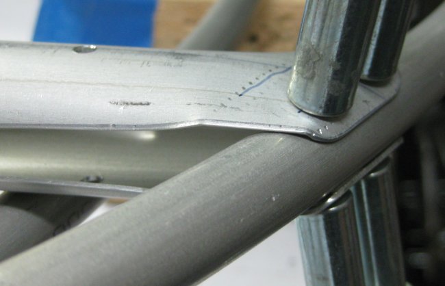
Elevator assemblies so far - now they need ribs!
12/8/11 - Elevator rib
1/2 hr - I either didn't cut or totally misplaced 1 elevator rib. So I went to the giant bunch of wing-related and spare tubes hanging on the wall, and the spare piece of the correct size was right there near the top. Rather than break out the chop saw, just used a plumbing tube cutter. It shrinks the cut end a little, but I put that on the to-be-reformed end. Then worked details of 1 rib. Fish-mouth - rough cut with the snips, then filed with the 1" round, touch up with the flat and scotchbrite wheel so it sits pretty snug on the spar tube. That makes what appears to be extra length in these ribs disappear. Then cut the wedge cut on the band saw. Not as bad as I thought, but I was glad I made that practice part - have to cut through both sides of the tube at once (obviously), except the far side can't be seen - so angle that in a little so as to not cut off too much, then flip the tube over and trim mostly to size. Smoothed the bandsawed edges with files, then drilled the rib to the elevator. Flattened the trailing edge of the rib with the hand seamer - much quicker and easier than a vise - how does one get one side of a V in a vise anyway? Marked the rib for the lacing holes. Will drill these separate on the drill press (pillar drill).
12/9/11 - Turned insert planning
1/2 hr - looked over the needs for lathe-turned tube inserts. After all that, I probably will end up buying another foot of 1.0 dia x .125 wall. So that will be a total of 9 feet, but just barely. Going to see a guy about some help with a lathe tomorrow, so I want a good list of what the parts are. The two that I dropped off the list are simple cut-to-length (the axle spacers).
12/9/11 - Elevator rib 2
3/4 hr - installed the 2nd rib into the elevator. This one had more extra stock on the aft end. Getting a little better at making the wedge cut up the tube with the band saw. Still needs the anti-bend straps (prevents the frame bending when the fabric is shrunk), and one of the two elevators will be designated for the trim tab - which looks about as complicated as building a whole other elevator, only smaller.
A thought from the fabric-covering class. One of the key points made in that class is everything shows through. So along that line, the elevator assembly sheet shows different numbers of lacing holes in each rib - one gets 8, the other gets 9. Well, when installed, the two ribs are only about 1/4" different in length, so I put 8 in each. One reason - the lacing (shows through the tapes) will look the same size. Also with 8 holes, I was thinking I could make 4 separate loops rather than lacing back to front and front to back. That way, if one lets go, the whole thing doesn't unravel. Now, that idea might not be of value because I don't know that a lacing loop would or wouldn't pull under a tape. Note - since these are tubular ribs, can't lace around them like is usual for a wing rib. Have to drill holes in the rib and lace right down the centerline. Downside to this is, there aren't little 1/2" wide laces every 3-4 inches - the lacing is going to sit on the outside as a line down the rib.
12/11/11 - Elevator ribs
1/4 hr - trimmed the lower elevator rib aft end to shape. Filed and scotchbrited the end.
12/12/11 - Elevator ribs
1/2 hr - trimmed and filed the upper rib aft end to shape. Drilled the rib lacing holes - to final size and deburred. Clecoed it back together. Put it aside and brought up the other elevator. Made the fishmouth on the lower rib for this one.
12/13/11 - Elevator / Rudder ribs
3/4 hr - fishmouthed the remaining elevator rib and the two rudder ribs. Cut the V slot on the bandsaw for all 4 ribs. Later, smoothed the V-cuts on the elevator ribs with file & scotchbrite wheel and pad. Got the two ribs drilled to the gusset plates at the forward end. Got the aft end of one of the ribs drilled to the trailing edge tube.
Full-length rib. Forward end drilled to spar. Aft end just sitting in place.
Line across rib at forward edge of trailing edge tube - this much of the rib has to be made flat.
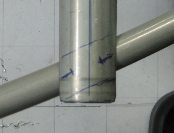
Line across rib aft of trailing edge tube - this is where the rib gets cut off. I used ~3/8" from the trailing edge tube centerline.
Rib flattened with hand seamer and cut to length.
Round the corners and bend the trailing edge down. I did this with the hand seamer off of the assembly, but the directions make reference to tap it with a hammer. Note - this lower rib was barely long enough. Might make the shorter of the elevator ribs ~5mm longer to start with.
This one had plenty of extra length to trim off.
12/14/11 - Elevator ribs
1/2 hr - filed the V-slot in the last elevator rib. Flattened it, then drilled it to the trailing edge tube. Marked for trimming. Trimmed, filed, scotchbrited the end of the rib. Bent the flange past the rivet holes with the hand seamer. Put rib back in place and bent the very back edge of the overhanging rib maybe a hair more with the rubber-faced hammer. This page is long enough. On to Tail 2 for the trim tab...
Click to join sherwoodbuilders