Sonex* Variations 1
*This web site is NOT owned or managed by Sonex, Ltd.. Sonex, Ltd. is not responsible for the content unless explicitly stated. See Disclaimer.
Reality is an exercise in damage control and error recovery. This is my "variations" page, where things did not go exactly according to print, but I made the determination that the parts were not quite scrap. Please, don't do anything shown on this page. These are my own personal damage control and error recovery exercises, and are absolutely not recommended for your own use.
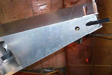
The two-piece bottom skin. CH801's use more pieces than this, divided similarly to this. But I will make a structural doubler to be inserted behind this skin and add rivets to make this splice stronger than a solid sheet.
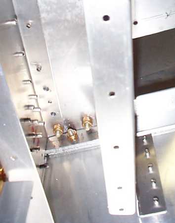
The cross beam behind the upper edge of the seat. I could not figure how to get the rivets into the cockpit-to-tailcone splice plate at this location, so I am running 2 3/16" bolts in place of the 3 rivets called out. Subject holes are just inboard of the most forward nut and bolt in the picture.

Same thing, other side.
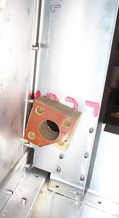
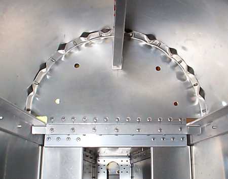
The prints that I used when starting the fuselage had a different type (more difficult to construct) fairlead setup. As such, I installed these through the tail box from forward. In drilling the stepped hole which allows the rivet to grip the block, I drilled all the way through in one location. So I sliced off the corner of the block, offset the hole, and maintained 4 rivets retaining the block.
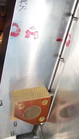
Same thing, other side. I think this problem originated because the fairlead block would get sucked into the drill bit out of the drill press vise.

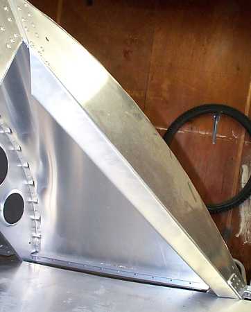
The right forward t-deck former - hammer formed over a block. This is not a structural issue, but there is a slight indentation at the form block thickness. The bottom skin is slipped under the t-deck in this picture - normally the area below the former is open to the tail cone.
Other side, showing a cleanly bent former. I don't recall what I did to make the bend better.
The aft most t-deck former - after all that fluting and tight bending, the part was too short to have good edge distance to the cross beam. So I made a splice plate with 2x the called out rivets at the joint.
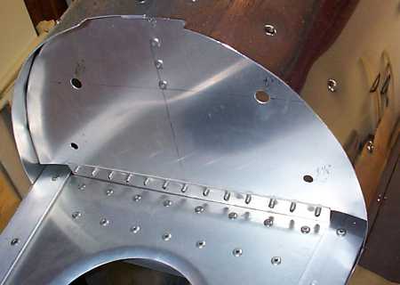
View of splice from "outside" (hidden inside tail fairings).
Screwed up the edge distance on the elevator hinge. Contacted Sonex about this one with my plan - place rivets at the correct edge distance between the incorrect ones. It's not terribly attractive, and I'm very tempted to make another tail. It was only about 35 hours work. I would re-use the same elevators. Just remove the hinge pin and they're still good for another horizontal stabilizer.

View of other side of h-tail. I added rivets on this side (all at correct edge distance) in an attempt to have the 2 sides look similar. Metal, especially bare metal, is merciless from an aesthetics standpoint. Sure, composite airplanes take longer to prep for paint than they do to build, but sheetmetal with exposed rivets can't be fixed - it can only be done over. (I've heard that RV's and others working with flush rivets & painted surfaces can & do use fill similar to composite airplanes to help achieve that smooth finish.)
Aft wing rib aft flanges have marginal edge distance. Black marker line shows expected rivet locations. There's only 4 rivets/rib here, loaded in tension, so shear failure due to edge distance is unlikely, and with the upper & lower rib flanges loaded in shear relative to this flange, plus with the rear spar rivets loaded in shear (and in much greater numbers than the 4 per rib bay on the rib), these will probably be ok. I may add 3 between the 4 at better edge distance as a sure fix.
More aft rib aft flanges.
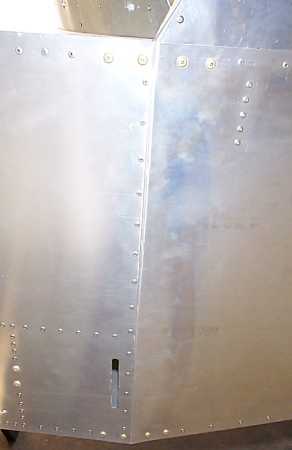
The left cockpit side does not meet the bend for the tailcone side exactly straight. This was done to ensure that the tail is level relative to the upper cockpit sides (tail level relative to wing) to take up slight misalignment built up in the assembly. Right side is straight.
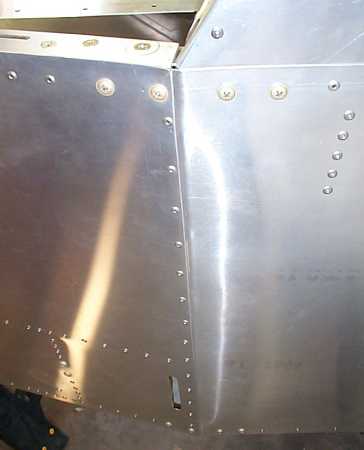
Another view. Total variation is just over 1/8 inch.